電源ボタンを入れると、マザーボードに供給されている電源が電源回路を経由し、チップセットに電力が供給される。マザーボードはATXの "Power good signal" を受ける。
ATX Power Good
The ATX specification defines the Power-Good signal as a +5-volt (V) signal generated in the power supply when it has passed its internal self-tests and the outputs have stabilized. This normally takes between 0.1 and 0.5 seconds after the power supply is switched on. The signal is then sent to the motherboard, where it is received by the processor timer chip that controls the reset line to the processor.
The ATX specification requires that the power-good signal ("PWR_OK") go high no sooner than 100 ms after the power rails have stabilized, and remain high for 16 ms after loss of AC power, and fall (to less than 0.4 V) at least 1 ms before the power rails fall out of specification (to 95% of their nominal value).
Cheaper and/or lower quality power supplies do not follow the ATX specification of a separate monitoring circuit; they instead wire the power good output to one of the 5 V lines. This means the processor will never reset given bad power unless the 5 V line drops low enough to turn off the trigger, which could be too low for proper operation.
Power Good values
Power good value is based on the delay in ms, that a power supply takes to become fully ready. Power good values are often considered abnormal if detected lower than 100ms or higher than 500ms.[1]
これによってCPUが起動する。レジスタにあるデータはすべてリセットされ、デフォルト値がセットされる。
IP              0xFFF0
CS selector     0xF000
CS base         0xFFFF0000
CPUはReal Modeで起動を始める。
x86互換CPUの動作モードで、これは8086から最新の64bit CPUまですべて共通している。メモリのアドレスバスは20bit(2^20bytes=1MB)の空間に分割し、すべてのプログラムが直接的にメモリにアクセスできる。
メモリ空間は1MBなのにregisterは16bitしかない。16bit registerが扱えるアドレスは最大で2^16(0xffff=64KB)。そのためセグメント方式が利用される。
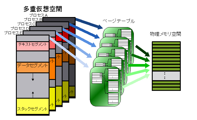
各セグメントは65535バイト(=64KB)の固定長に分割される。16bit registerでは、64KBを超えるメモリアドレスにアクセスができないため、セグメントアドレス:オフセットアドレスの組み合わせで構成される。メモリの物理アドレスを算出するためには、セグメントアドレスに16を掛けてオフセットアドレスを足す。
CS(セグメントアドレス):IP(オフセットアドレス)
0x2000:0x0010 の場合
対象となるアドレスは
hex ((0x2999 << 4) + 0x1000)
= 0x20010
つまり初期化で実際に行われている前述内容
IP              0xFFF0
CS base         0xFFFF0000
これを物理アドレスで表現すると
0xffff000:0xfff0
となる。これがCPU起動時のリセット処理であり、最大4GBのメモリ空間にアクセス可能となる。これをReset Vectorと呼ぶ。
Reset Vectorによって、CPUのすべての初期化が終わった時点で最初に行う命令がこのアドレスに入っている。
Reset Vectorの指定先アドレスには jump 命令(JMP命令)が入っている。通常はBIOSのエントリポイントが指定されている。

coreboot-4.0のソースコードから(src/cpu/x86/16bit/reset16.incより)
.section ".reset".code16.globl reset_vector reset_vector: .byte 0xe9 .int _start - ( . + 2 ) . = 0x8; .code32 jmp protected_start .previous
0xe9についてはこちら。
/*
 _ROMTOP                 : The top of the rom used where we
 need to put the reset vector.
 */
 SECTIONS {
     /* Trigger an error if I have an unuseable start address */
     _bogus = ASSERT(_start >= 0xffff0000, "_start too low. Please decrease CONFIG_ROM_IMAGE_SIZE");
     _ROMTOP = 0xfffffff0;
     . = _ROMTOP;
     .reset . : {
         *(.reset)
         . = 15 ;
         BYTE(0x00);
     }
 }
BIOSの実行。ハードウェアの初期化とチェック。ブート可能デバイスの探索。ブート順はBIOSに保存されている。ハードディスクから起動する場合はBIOSはディスクのブートセクタを探索する。ハードディスクがMBR(Master Boot Record)でパーティショニングされている場合はブートセクターは最初の512バイト(セクター)の最初の446バイトに存在する。最初のセクターの最後の2バイトは 0x55 と 0xaa で、BIOSに対してこのデバイスがブータブル(起動可能)であることを知らせる役目がある。
BIOSはこの最初の512バイトのロードしか保証しない。
当然この512バイトには次のプログラムをロードするプログラムが存在しなければならない。
一般的にはGRUBやLILOが使われている部分である。(Bootloader)

コメント